What is a Pressure Relief Valve and How Does it Work?
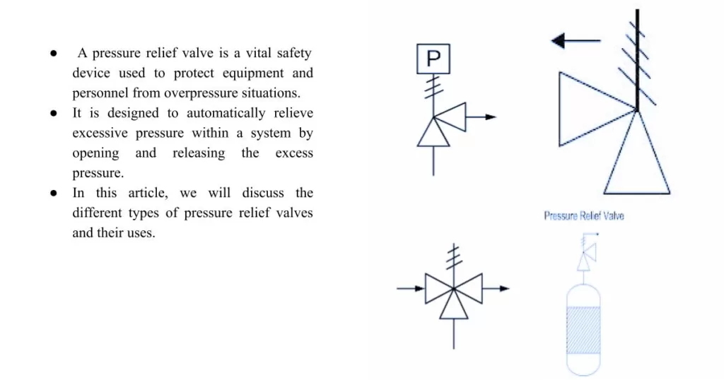
A pressure relief valve is a vital safety device used to protect equipment and personnel from overpressure situations. It is designed to automatically relieve excessive pressure within a system by opening and releasing the excess pressure. In this article, we will discuss the different types of pressure relief valves and their uses.
Types of Pressure Relief Valves:
- Safety Valves: These valves are the most common type of pressure relief valve and are typically used in steam boilers and other high-pressure systems. They are designed to open when the pressure inside the system exceeds a pre-set level, and then close when the pressure returns to a safe level.
- Pressure-Reducing Valves: These valves are used to reduce the pressure of a fluid stream before it enters a downstream system. They are commonly used in pipelines, water supply systems, and HVAC systems.
- Vacuum Relief Valves: These valves are designed to prevent the formation of a vacuum in a system that could cause damage or collapse. They are commonly used in storage tanks, pipelines, and other closed systems.
- Thermal Relief Valves: These valves are used to relieve pressure caused by thermal expansion in a closed system. They are commonly used in water heaters, boilers, and other heat transfer systems.
Uses of Pressure Relief Valves:
- Protection of Equipment: Pressure relief valves are used to protect equipment from damage caused by overpressure situations. This includes boilers, pipelines, storage tanks, and other pressure vessels.
- Personnel Safety: Pressure relief valves are also used to protect personnel from injury or death caused by overpressure situations. This is especially important in industries such as oil and gas, chemical processing, and power generation.
- Environmental Protection: In addition to protecting equipment and personnel, pressure relief valves are also used to protect the environment from damage caused by overpressure situations. This includes preventing spills and releases of hazardous materials.
Download Pressure Relief Valves: Types PDF
Choosing the Perfect Pressure Relief Valve:
A Step-by-Step Guide to Selection and Sizing, Pressure relief valves are critical safety devices that protect equipment, personnel, and the environment from overpressure situations. Selecting the right pressure relief valve is crucial to ensure its effectiveness in preventing catastrophic failures.
When selecting a pressure relief valve, the following properties must be considered:
- Set Pressure: The set pressure is the pressure at which the valve begins to open and relieve pressure. It is typically set slightly above the maximum operating pressure of the system to provide a safety margin.
- Capacity: The capacity of a pressure relief valve is the amount of fluid that can be discharged through the valve in a given period. It is typically expressed in terms of flow rate or discharge coefficient.
- Materials of Construction: The materials of construction must be compatible with the fluid being handled and the operating conditions of the system. This includes considerations such as temperature, pressure, corrosion resistance, and mechanical properties.
- End Connections: The end connections of the pressure relief valve must be compatible with the piping system it is being installed in. Common end connections include threaded, flanged, and welded connections.
- Codes and Standards: The selection of a pressure relief valve must comply with relevant codes and standards such as ASME Boiler and Pressure Vessel Code, API Standard 526, and National Board Inspection Code.
The selection of the pressure relief valve must comply with relevant codes and standards, such as ASME Section VIII, Division 1.
All Part List of Pressure Relief Valve with Uses:
The uses of each part of the pressure relief valve are as follows:
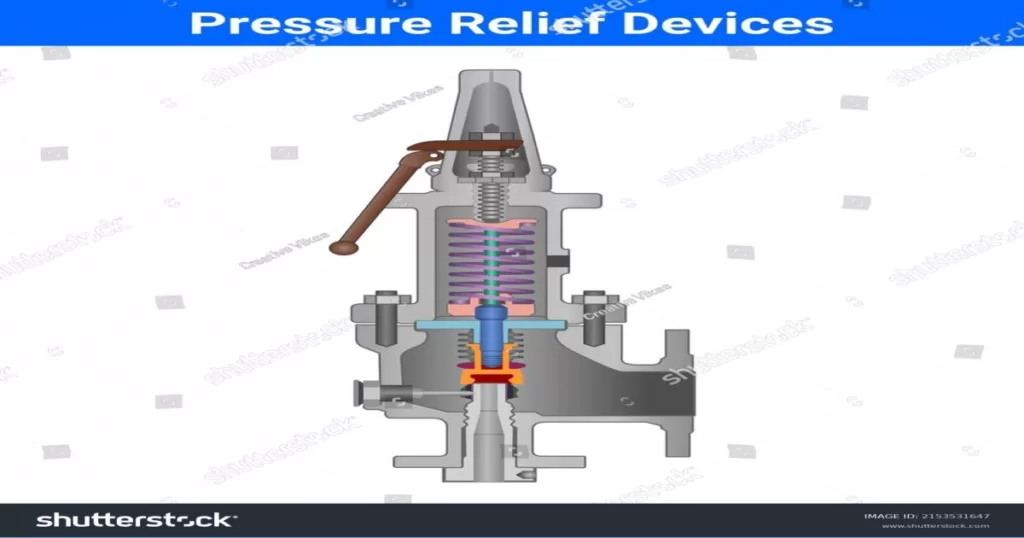
- Valve Body: The valve body provides a sturdy housing for the internal components of the pressure relief valve and also provides a connection point for the piping system.
- Disc: The disc is the key component that lifts off the seat to relieve pressure in the system. It must be made of a strong and durable material to withstand the forces of high-pressure fluid flows.
- Seat: The seat is the sealing surface that the disc rests on when the valve is closed. It must be made of a material that can withstand the high-pressure environment and remain leak-free.
- Spring: The spring provides the force that holds the disc against the seat and determines the set pressure of the valve. It must be calibrated correctly to ensure that the valve opens at the correct pressure.
- Bonnet: The bonnet covers the top of the valve body and provides access to the internal components for maintenance and repair. It must be designed to withstand the high-pressure environment and remain leak-free.
- Nozzle: The nozzle directs the flow of fluid from the valve into the downstream piping. It must be designed to ensure that the flow is directed appropriately to prevent damage to downstream equipment.
- Flange: The flange provides a connection point for the valve to be mounted to the piping system. It must be designed to ensure a secure and leak-free connection.
Codes and Metrology Standards use in pressure relief valve:
When selecting and installing a pressure relief valve, it is important to comply with relevant codes and standards to ensure the safety and reliability of the system. Some of the commonly used codes and standards include:
- ASME Boiler and Pressure Vessel Code: This code provides standards for the design, construction, and testing of pressure vessels and pressure relief valves.
- API Standard 526: This standard provides guidelines for the selection, sizing, and installation of pressure relief valves in oil and gas applications.
- National Board Inspection Code: This code provides requirements for the inspection, testing, and certification of pressure relief valves.
- ISO 4126: This standard provides guidelines for the selection, installation, and maintenance of pressure relief valves.
- ANSI/ISA-84.00.01: This standard provides guidelines for the design, installation, and maintenance of safety instrumented systems.
Complying with relevant codes and standards ensures that pressure relief valves are installed and maintained properly, reducing the risk of equipment failure and ensuring the safety of personnel and the environment.
Tailoring Pressure Relief Valve Solutions:
Meeting Specific Requirements for Diverse Industrial Applications, Pressure relief valves have specific requirements for their use to ensure that they function properly and provide the necessary level of safety. Here are some of the specific requirements for using pressure relief valves:
- Proper Sizing: Pressure relief valves must be properly sized to ensure that they can handle the flow of fluid through the pipeline without causing excessive pressure drop or damage to the valve.
- Set Pressure: The set pressure of the valve must be carefully determined based on the maximum pressure that the pipeline is designed to handle.
- Installation: Pressure relief valves must be installed in the correct orientation and location to ensure that they can function properly in the event of an overpressure situation.
- Maintenance: Pressure relief valves must be regularly inspected and maintained to ensure that they remain in good working condition.
- Testing: Pressure relief valves must be tested periodically to ensure that they are functioning properly and that they can relieve pressure in the event of an overpressure situation.
Size and Type Calculation for Pressure Relief Valves in Pipelines:
The size and type of pressure relief valve required for a pipeline depends on several factors, including the size of the pipeline, the type of fluid being transported, and the maximum allowable working pressure (MAWP) of the pipeline. Here is a formula for calculating the required size of a pressure relief valve for a pipeline:
Q = C x A x P x K
- Where: Q = Flow rate in cubic feet per minute (CFM)
- C = Discharge coefficient
- A = Cross-sectional area of the valve inlet in square inches
- P = Pressure in pounds per square inch (PSI) at the valve inlet
- K = Correction factor for the specific gravity of the fluid
Here is an example calculation using this formula:
Assume we have a pipeline with a 10-inch diameter and a MAWP of 1500 PSI, transporting propane with a specific gravity of 1.55. We want to calculate the required size of the pressure relief valve to be installed on the pipeline.
First, we need to calculate the cross-sectional area of the valve inlet:
- A = (π/4) x D^2
- A = (π/4) x 10^2
- A = 78.54 square inches
Next, we need to determine the discharge coefficient for the valve. This can be found in manufacturer’s data sheets or through testing.
- Assuming a discharge coefficient of 0.725, we can calculate the required flow rate as follows:
- Q = 0.725 x 78.54 x 1500 x 0.69
- Q = 73,233 CFM
Based on this calculation, we would need to install a pressure relief valve with an inlet size of at least 10 inches to ensure that it can handle the required flow rate in the event of an overpressure situation.
It is important to note that there are several types of pressure relief valves available, including spring-loaded, pilot-operated, and bellows-type valves. The type of valve required for a pipeline will depend on the specific application and requirements. Proper sizing and selection of the valve type is critical to ensuring the safety and reliability of the pipeline.
Code and Standards for Pressure Relief Valve Parts:
A Guide to Ensuring Quality and Reliability in Selection, When selecting a pressure relief valve, it is important to consider the applicable codes and standards to ensure that the valve is designed and manufactured to the appropriate specifications for the specific application. Here are some of the codes and standards commonly used in pressure relief valve selection:
- ASME Section VIII: This code provides guidelines for the design, fabrication, inspection, and testing of pressure vessels and pressure relief valves.
- API 526: This standard specifies the requirements for pressure relief valves used in the oil and gas industry, including sizing, selection, and installation.
- ANSI/ISA-84.00.01: This standard provides guidance on the design, installation, and operation of safety instrumented systems (SIS) for the process industry, including pressure relief valves.
- ISO 4126: This standard provides guidance on the design, selection, and installation of pressure relief valves, including sizing, testing, and maintenance requirements.
- EN 764-7: This European standard provides guidance on the design, selection, and installation of pressure relief valves for use in pressure equipment.
Valve leakage classes are:
- Class I – Valve leakage rate not to exceed 0.01% of valve rated capacity.
- Class II – Valve leakage rate not to exceed 0.5% of valve rated capacity.
- Class III – Valve leakage rate not to exceed 5% of valve rated capacity.
- Class IV – Valve leakage rate not to exceed 10% of valve rated capacity.
- Class V – Valve leakage rate not to exceed 25 drops per minute per inch of port diameter for port sizes up to 2 inches, and not to exceed 40 drops per minute for port sizes larger than 2 inches.
- Class VI – Valve leakage rate not to exceed 0.01% of valve rated capacity or 50 ppm, whichever is less.
It is important to select the appropriate leakage class for the valve based on the specific application and requirements to ensure safe and reliable operation.
How to Calculate Pressure Drop in Pressure relief Valves
Pressure Drop Calculation for Pressure Relief Valve: The pressure drop across a pressure relief valve can be calculated using the following formula:
ΔP = (Cv / K) x (Q / G)^2
where ΔP is the pressure drop in psi, Cv is the valve flow coefficient, K is the specific gravity correction factor, Q is the flow rate in gallons per minute, and G is the specific gravity of the fluid.
When selecting a pressure relief valve, it is important to ensure that the pressure drop across the valve is within acceptable limits to prevent excessive energy loss and potential damage to the system.
Comparison of Pressure Relief Valve vs Gate Valve:
Pressure relief valves and gate valves serve different purposes in a piping system. A pressure relief valve is designed to protect against overpressure conditions by relieving excess pressure from the system, while a gate valve is designed to regulate flow by opening or closing the valve.
Pressure relief valves are typically used in applications where the potential for overpressure conditions exists, such as in boilers, pressure vessels, and pipelines. Gate valves, on the other hand, are used to control flow in a variety of applications, such as water distribution, oil and gas pipelines, and wastewater treatment plants.
While there are some similarities between pressure relief valves and gate valves, such as the use of a valve body and sealing mechanism, they are fundamentally different in their design and function.
Comparison of Pressure Relief Valve vs Pressure Control Valve:
A pressure relief valve and a pressure control valve are both designed to regulate pressure in a piping system, but they serve different purposes. A pressure relief valve is designed to protect against overpressure conditions by relieving excess pressure from the system, while a pressure control valve is designed to maintain a set pressure within a system.
Pressure relief valves are typically used in applications where the potential for overpressure conditions exists, such as in boilers, pressure vessels, and pipelines. Pressure control valves, on the other hand, are used to maintain a specific pressure in a system, such as in HVAC systems, water treatment plants, and industrial processes.
While both types of valves are important for maintaining safe and reliable operation of piping systems, they are fundamentally different in their design and function, and are used in different applications.
Comparison of Pressure Relief Valve vs Pressure Safety Valve vs pilot PSV:
Pressure relief valves, pressure safety valves, and pilot PSVs all serve the purpose of protecting a piping system against overpressure conditions. However, they have some differences in their design and function.
- A pressure relief valve is designed to relieve excess pressure from a system by opening when the pressure exceeds a set point. It then closes when the pressure drops below the set point. Pressure relief valves are typically used in applications such as boilers, pressure vessels, and pipelines.
- A pressure safety valve, also known as a pressure relief valve, operates in a similar way to a pressure relief valve. However, it is typically used in high-pressure applications, such as oil and gas pipelines, where the potential for catastrophic failure is high.
- A pilot PSV is designed to measure the pressure of a fluid flowing through a pipeline or other system. It consists of a pilot tube that is inserted into the flow of the fluid, and a pressure gauge that measures the pressure difference between the pilot tube and a reference point. Pilot PSVs are typically used in applications such as water distribution systems and HVAC systems.
When selecting a pressure relief device for a specific application, it is important to consider the operating conditions and specific requirements of the system to determine which type of device is most appropriate.
Pressure Relief Valve Installation Checklist:
- Verify that the valve is the correct type and size for the application.
- Ensure that the valve is installed in the correct orientation.
- Verify that the valve is installed in the correct location to protect against overpressure conditions.
- Check that the valve is properly secured and supported.
- Ensure that the valve is properly aligned with the piping system.
- Verify that the valve is properly connected to the piping system.
- Check that all gaskets and seals are properly installed and tightened.
- Verify that the valve is properly vented to prevent back-pressure buildup.
- Check that all required accessories, such as isolation valves and pressure gauges, are properly installed.
- Perform a pressure test to verify that the valve is operating correctly.
Pressure Relief Valve Inspection Checklist:
- Check that the valve is properly installed and supported.
- Verify that the valve is properly aligned with the piping system.
- Inspect all gaskets and seals for signs of wear or damage.
- Verify that the valve is properly vented to prevent backpressure buildup.
- Check that all required accessories, such as isolation valves and pressure gauges, are properly installed.
- Inspect the valve for signs of leakage or damage.
- Verify that the valve is properly labeled with the appropriate pressure rating and set pressure.
- Check that the valve is set to the correct pressure.
- Verify that the valve is properly calibrated and functioning correctly.
- Record all inspection results and take corrective action as necessary.
Pressure relief valves can fail to operate correctly for various reasons, which can result in overpressure conditions that could damage the piping system or cause a safety hazard. Some common causes of failure include:
- Improper installation: If the valve is not installed correctly or is not aligned properly, it may not operate correctly.
- Dirt or debris: Dirt or debris can accumulate in the valve and prevent it from opening or closing properly.
- Corrosion: Corrosion can damage the valve seat or other components, which can prevent the valve from sealing properly.
- Wear and tear: Over time, the valve components can wear out and lose their effectiveness.
- Improper maintenance: If the valve is not properly maintained or inspected regularly, it may not operate correctly.
Troubleshooting pressure relief valves
involves identifying the cause of the problem and taking appropriate corrective action. Some troubleshooting steps include:
- Inspecting the valve for damage or wear.
- Cleaning the valve to remove dirt or debris.
- Adjusting the valve set pressure to the correct level.
- Replacing damaged or worn components.
- Calibrating the valve to ensure that it is operating correctly.
