Centrifugal compressor (Api 617)
The centrifugal compressor is a type of compressor commonly used in various industries for compressing gases. It operates on the principle of dynamic compression, where the kinetic energy of the gas is converted into pressure energy. The API 617 is a standard published by the American Petroleum Institute (API) that provides guidelines for the design, manufacturing, and operation of centrifugal compressors in the petroleum, petrochemical, and natural gas industries.
Here are some key features and considerations related to centrifugal compressors according to API 617:
Design and Construction:
- Impellers: Centrifugal compressors have multiple impellers mounted on a shaft. These impellers rotate at high speeds, imparting kinetic energy to the gas.
- Casings: The impellers are housed within casings that provide structural support and help direct the flow of gas. The casings are designed to handle high-pressure differentials and are typically made of materials suitable for the process conditions.
- Bearings: The compressor shaft is supported by bearings that allow smooth rotation and help maintain proper alignment. API 617 specifies requirements for the design, selection, and installation of bearings.
- Seals: Centrifugal compressors require seals to prevent gas leakage along the shaft. Various types of seals, such as labyrinth seals or mechanical seals, may be used. The standard provides guidelines for seal selection and performance.
Operational Considerations:
- Performance: API 617 outlines requirements for the performance characteristics of centrifugal compressors, including efficiency, pressure ratio, and capacity. Compressors should be designed to meet the specified performance criteria.
- Mechanical Integrity: The standard emphasizes the importance of mechanical integrity, including factors such as rotor dynamics, vibration, and balancing. Proper design and maintenance practices are essential to ensure reliable and safe operation.
- Safety: API 617 addresses safety considerations, such as compressor protection systems, anti-surge control, and emergency shutdown procedures. These measures help prevent compressor failures, which can have severe consequences.
- Testing and Inspection: The standard provides guidance on testing and inspection requirements for centrifugal compressors. It covers aspects like performance testing, material testing, non-destructive examination, and quality assurance during manufacturing.
It’s important to note that the API 617 standard is comprehensive and covers many more aspects related to centrifugal compressors, including materials, lubrication, auxiliary systems, and documentation. Consulting the API 617 standard itself or seeking expert advice is recommended for detailed information and compliance with the requirements.
 |
| IMPELLER ASSEMBLY |
Compressor driver
A compressor driver refers to the prime mover or the device responsible for providing the mechanical power required to drive a compressor. The driver’s role is to supply the energy needed to rotate the compressor’s shaft, which in turn drives the impellers or rotors to compress the gas.
Various types of compressor drivers are used based on the specific application and requirements. Some common types of compressor drivers include:
- Electric Motors: Electric motors are widely used as compressor drivers, especially in applications where a reliable power supply is available. They can be easily controlled, have high starting torque, and offer efficient operation. Electric motors are commonly used for small to medium-sized compressors.
- Gas Turbines: Gas turbines are often employed as drivers for large-scale compressors, particularly in industrial and oil and gas applications. They use the combustion of a fuel-air mixture to drive a turbine, which is connected to the compressor. Gas turbines provide high power outputs and are suitable for continuous operation.
- Steam Turbines: Steam turbines utilize steam generated from a boiler to drive the turbine and, consequently, the compressor. These drivers are commonly used in applications where steam is readily available, such as in power plants and industrial processes. Steam turbines offer good efficiency and can handle large capacity requirements.
- Internal Combustion Engines: Internal combustion engines, powered by fuels like diesel or natural gas, can serve as compressor drivers in certain applications. They are often used in remote or mobile operations where electrical power may not be accessible. Internal combustion engines offer flexibility, portability, and can be used in various industries.
- Hydraulic Drivers: In some cases, hydraulic systems are employed as compressor drivers. Hydraulic drivers use pressurized fluids to generate rotational motion, which is then transmitted to the compressor. These systems are typically used in specialized applications where other types of drivers may not be suitable.
The selection of a compressor driver depends on factors such as the required power output, operational efficiency, availability of energy sources, and specific application needs. Manufacturers and engineers consider these factors while designing compressor systems to ensure optimal performance and reliability.
Coupling
A compressor coupling refers to the mechanical connection between the compressor driver and the compressor itself. It is used to transmit the power from the driver to the compressor, allowing the driver to rotate the compressor’s shaft and drive the compression process. The coupling serves as a means to join the two components together while accommodating misalignment and allowing for maintenance and removal of the compressor.
There are several types of couplings commonly used in compressor systems:
- Gear Coupling: Gear couplings consist of two hubs with external teeth that mesh together. They provide high torque transmission capabilities and can accommodate angular misalignment between the driver and compressor. Gear couplings are commonly used in large compressors that require high torque and can handle heavy loads.
- Grid Coupling: Grid couplings use a flexible grid element to transmit torque. They are designed to provide high misalignment capacity, damping of vibrations, and ease of maintenance. Grid couplings can accommodate both angular and axial misalignment, making them suitable for various compressor applications.
- Flexible Disc Coupling: Flexible disc couplings utilize thin metal discs or plates that are bolted between the driver and compressor. These discs allow for some misalignment while transmitting torque. Flexible disc couplings are known for their compact design, high torsional stiffness, and ability to absorb shock loads.
- Jaw Coupling: Jaw couplings consist of two hubs with interlocking teeth that engage with an elastomeric spider. They are easy to install, provide some degree of misalignment tolerance, and have good damping characteristics. Jaw couplings are commonly used in smaller compressor applications.
- Torsional Coupling: Torsional couplings are designed to minimize the transmission of torsional vibrations between the driver and compressor. They are used to protect the compressor from damaging torsional forces and to enhance system reliability. Torsional couplings may incorporate features such as rubber elements or elastomeric inserts to absorb vibrations.
The selection of a compressor coupling depends on factors such as the power requirements, misalignment capacity, torque transmission capabilities, and the specific application conditions. Manufacturers and engineers consider these factors to ensure that the coupling can effectively and reliably transmit power while accommodating any misalignment between the driver and compressor.
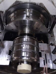
Dry gas seal
A compressor coupling refers to the mechanical connection between the compressor driver and the compressor itself. It is used to transmit the power from the driver to the compressor, allowing the driver to rotate the compressor’s shaft and drive the compression process. The coupling serves as a means to join the two components together while accommodating misalignment and allowing for maintenance and removal of the compressor.
There are several types of couplings commonly used in compressor systems:
- Gear Coupling: Gear couplings consist of two hubs with external teeth that mesh together. They provide high torque transmission capabilities and can accommodate angular misalignment between the driver and compressor. Gear couplings are commonly used in large compressors that require high torque and can handle heavy loads.
- Grid Coupling: Grid couplings use a flexible grid element to transmit torque. They are designed to provide high misalignment capacity, damping of vibrations, and ease of maintenance. Grid couplings can accommodate both angular and axial misalignment, making them suitable for various compressor applications.
- Flexible Disc Coupling: Flexible disc couplings utilize thin metal discs or plates that are bolted between the driver and compressor. These discs allow for some misalignment while transmitting torque. Flexible disc couplings are known for their compact design, high torsional stiffness, and ability to absorb shock loads.
- Jaw Coupling: Jaw couplings consist of two hubs with interlocking teeth that engage with an elastomeric spider. They are easy to install, provide some degree of misalignment tolerance, and have good damping characteristics. Jaw couplings are commonly used in smaller compressor applications.
- Torsional Coupling: Torsional couplings are designed to minimize the transmission of torsional vibrations between the driver and compressor. They are used to protect the compressor from damaging torsional forces and to enhance system reliability. Torsional couplings may incorporate features such as rubber elements or elastomeric inserts to absorb vibrations.
The selection of a compressor coupling depends on factors such as the power requirements, misalignment capacity, torque transmission capabilities, and the specific application conditions. Manufacturers and engineers consider these factors to ensure that the coupling can effectively and reliably transmit power while accommodating any misalignment between the driver and compressor.
 |
| TRUST BEARING |
Part of centrifugal com pressure
The components you mentioned are essential parts of a centrifugal compressor. Let’s briefly discuss each component:
- Compressor Shaft: The compressor shaft connects the driver to the impeller. It transmits the rotational motion from the driver to the impeller, allowing it to compress the gas.
- Impeller: The impeller is a rotating component with curved blades or vanes. It accelerates the gas and imparts kinetic energy to it. The impeller’s design and geometry play a crucial role in determining the compressor’s performance.
- Labyrinth Seal: Labyrinth seals are used to prevent gas leakage along the compressor shaft. They consist of a series of stationary and rotating fins or teeth that create a tortuous path for the gas, minimizing leakage.
- Bearings: Bearings support the compressor shaft and allow it to rotate smoothly. They help maintain proper alignment and reduce friction and wear. Different types of bearings, such as journal bearings or ball bearings, may be used depending on the compressor design.
- Balancing Disk: Balancing disks, also known as balance pistons, are used to counteract axial thrust forces generated by the impeller. They help minimize the axial load on the bearings, ensuring stable and reliable operation.
- Balancing Drum: Balancing drums are used in some centrifugal compressors to counteract radial forces on the impeller. They are designed to balance the pressure differentials across the impeller and reduce vibration.
- Dry Gas Seal: Dry gas seals are advanced sealing systems used to prevent gas leakage in high-pressure applications. They utilize a set of rotating and stationary sealing rings to create a barrier against gas leakage along the shaft.
- Diaphragm Diffuser: The diaphragm diffuser is a component that helps convert the high-velocity gas flow from the impeller into high-pressure flow. It slows down the gas velocity and directs it to the discharge nozzle.
- Impeller Vanes: Impeller vanes are the curved blades or channels on the impeller. They control the gas flow and impart the necessary kinetic energy to the gas.
- Outlet and Inlet Nozzles: The outlet nozzle directs the compressed gas from the impeller to the discharge system, while the inlet nozzle guides the incoming gas into the impeller. These nozzles are designed to optimize gas flow and minimize losses.
What is rotor assembly?
The rotor assembly of a centrifugal compressor refers to the rotating components within the compressor, including the impeller(s) and the compressor shaft. The impeller(s) are mounted on the shaft, and when the shaft rotates, it imparts kinetic energy to the gas, causing it to move and be compressed. The rotor assembly is a critical part of the compressor responsible for the compression process.
What is the lube oil system in a centrifugal compressors?
The lube oil system in a centrifugal compressor is a subsystem that provides lubrication and cooling to the compressor’s bearings and other moving parts. It typically consists of an oil reservoir, an oil pump, oil filters, coolers, and a distribution network. The lube oil system ensures smooth operation, reduces friction and wear, and helps dissipate heat generated during compression, thereby prolonging the life of the compressor.
What is a dry gas seal?
A dry gas seal is an advanced sealing system used in centrifugal compressors to prevent gas leakage along the compressor shaft. Unlike traditional oil-based seals, dry gas seals do not require external lubrication. They consist of rotating and stationary seal rings with a small gap between them. The seal rings create a gas-tight barrier, effectively sealing the high-pressure gas within the compressor and preventing its escape.
What is the working principle of a centrifugal compressor?
Centrifugal compressors operate on the principle of dynamic compression. The working principle involves the following steps:
- The gas enters the compressor through the inlet nozzle and passes into the rotating impeller(s).
- As the impeller rotates, it imparts kinetic energy to the gas, causing it to accelerate and move radially outward.
- The gas moves through the impeller vanes, where it experiences an increase in velocity and a decrease in pressure due to centrifugal force.
- The gas then enters the diffuser, where its velocity decreases, and the kinetic energy is converted into pressure energy.
- Finally, the compressed gas is discharged through the outlet nozzle at a higher pressure.
How does a centrifugal compressor work?
A centrifugal compressor works by converting the kinetic energy of the gas into pressure energy through the following steps:
- The gas enters the compressor through the inlet and is directed to the rotating impeller(s).
- The impeller(s) accelerate the gas, imparting kinetic energy and increasing its velocity.
- The gas flows through the impeller vanes, where it experiences a decrease in pressure due to centrifugal force and an increase in kinetic energy.
- The gas then enters the diffuser, where its velocity decreases, and the kinetic energy is converted into pressure energy, resulting in compressed gas.
- Finally, the compressed gas is discharged through the outlet at a higher pressure.
What is a diffuser in a centrifugal compressor?
A diffuser in a centrifugal compressor is a component located after the impeller(s). It is designed to slow down the high-velocity gas flow exiting the impeller and convert the kinetic energy into pressure energy. The diffuser provides a gradually expanding passage that allows the gas to decelerate, recover pressure, and transform the kinetic energy into static pressure before it is discharged from the compressor.
What is a multistage centrifugal compressor?
A multistage centrifugal compressor is a compressor that consists of multiple stages, each comprising an impeller and a diffuser. In a multistage configuration, the gas is compressed in several consecutive stages, with each stage increasing the pressure incrementally. The compressed gas from one stage becomes the inlet for the next stage, allowing for higher overall pressure ratios. Multistage centrifugal compressors are used for applications requiring high compression ratios or when the gas pressure needs to be increased significantly.
What do you mean by compression stage?
Compression stage
Sometimes one impeller and one diaphragm define a stage. In other cases, however, a stage is defined from the beginning of a suction port to the end of a discharge port in this case. The stage could have more than one impeller in it.
In any case the gas leaving one stage will always be at a lower pressure than when at least the next stage in this way pressure is increased in each stage until the final pressure is reached.
And most of stage compressors the gas leaving an impeller of one stage flows through a shaft and around a diaphragm is then directed by the inlet guide into the eye of the next impeller.
Thanks for learn to learn more about Reciprocating pump click here
